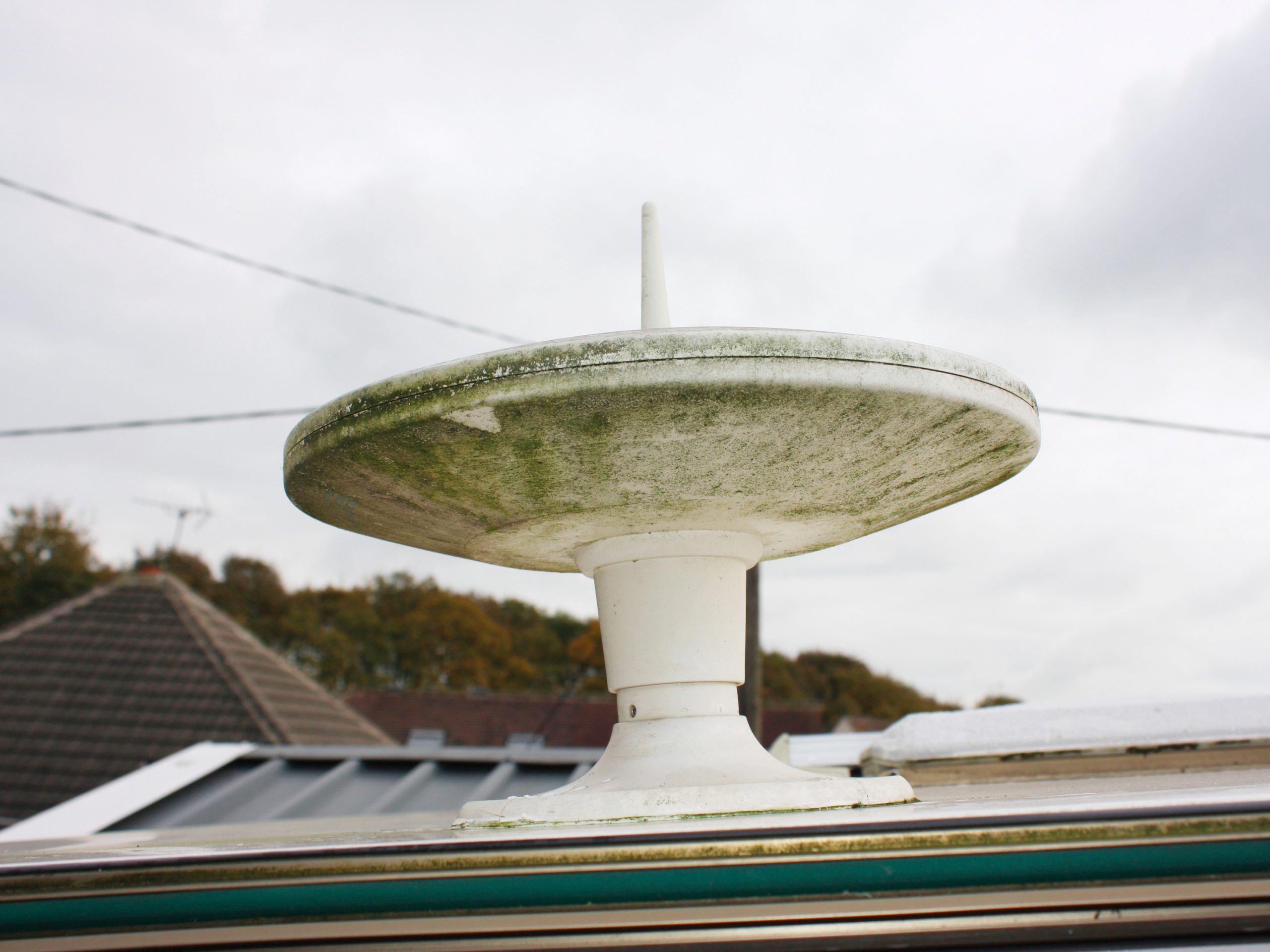


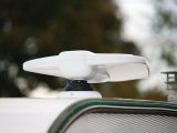
The original Status omni-directional TV antenna on my parents’ 17-year-old caravan was not performing as well as the latest generation of directional units. It needed updating. Read on to find out how we did it.
We chose a Vision Plus Status 570. The manufacturer seems to have thought about everything when it comes to fitting its products.
The antenna was for a 1999 Abbey GTS 215, which has a curved roof profile, and I had concerns that I wouldn’t be able to fit the antenna vertically.
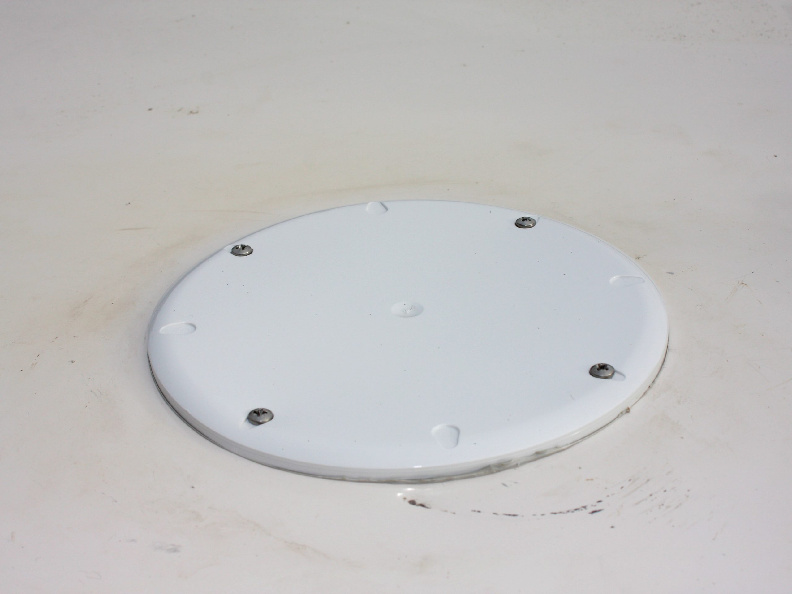
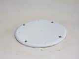
However, an angle-adjustable roof mount is available, catering for angles of up to 15°. I also acquired a blanking plate, which fits directly over the space left by the old antenna.
Getting started
The company advises, where possible, to fit the antenna on the tourer’s offside to avoid possible damage when in transit.
However, to have done so would have involved rewiring the van, so the exercise was almost a direct replacement of the original.
Tools for the job are:
- Crosshead screwdriver
- 2.5mm hexagonal allen key
- Sealant
- Electric drill and a small bit
- 50mm hole-cutter
- Spirit level
- Washing-up liquid
First, ensure that the van is level – it’s hard to gauge the vertical otherwise.
Remove the old antenna. The coaxial cable will need to be undone from the old amplifier and any cable fasteners removed.
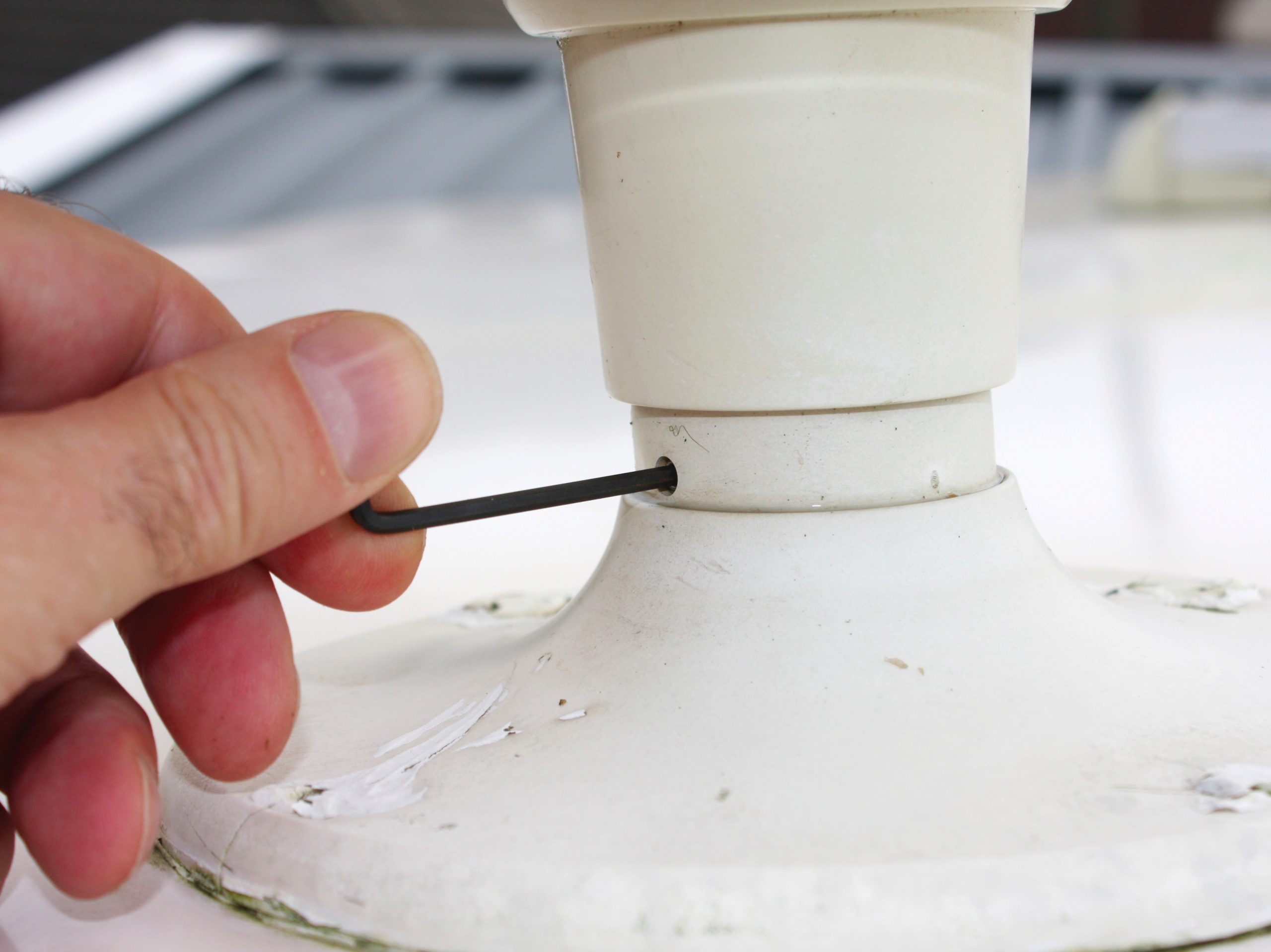
The two 2.5mm grub screws that secure the antenna to its base will need releasing using an allen key. The antenna should lift out of its base (along with the coaxial cable).
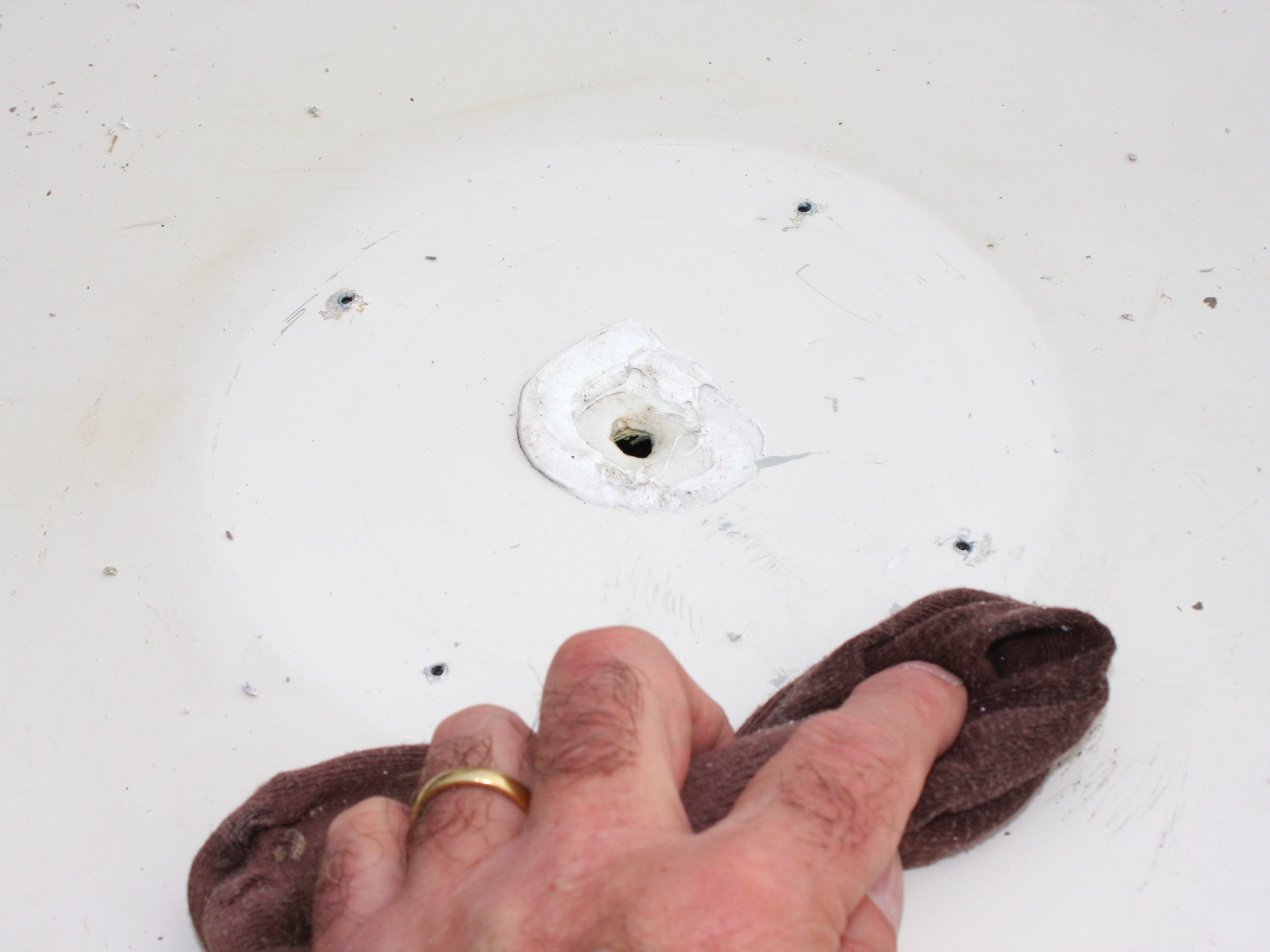
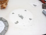
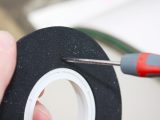
The most difficult part of the operation is removing the original mount. After prising out old sealant from the screw holes, remove the four crosshead screws that hold the mount to the roof.
Our mount had been well sealed to the roof, but with careful use of scrapers, it came off. Clean off all the old sealant.
Like-for-like
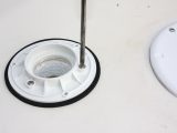
When the roof is clean, apply tape-type sealant to the new blanking plate and attach to the roof using the same screw holes that had secured the old antenna. Trim off any excess sealant.
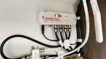
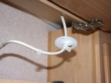
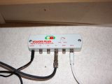
Remove the old amplifier, but retain the 12V supply (which is the same as the new one) and the TV/radio connections, which can be reused.
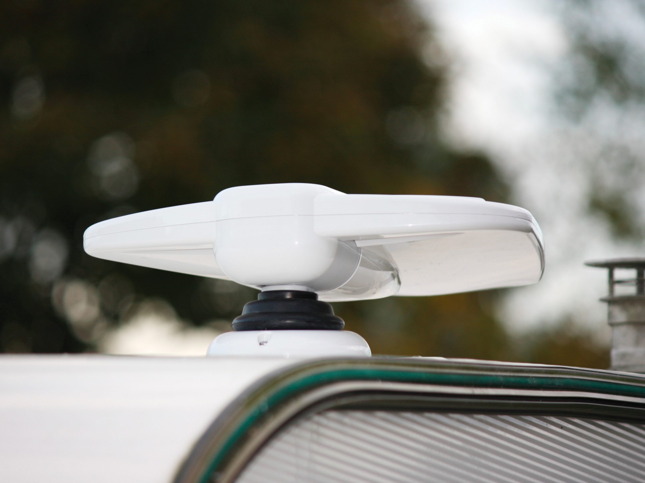
When it came to locating the new antenna, the overhead locker in front of the original wiring was perfect, and deep enough for the mast (the intrusion being between 280mm and 305mm). The centre of the hole for the mast needs to be at least 50mm from any wall.
A template is provided in the instructions. If fitting an angle-adjustable mount, ensure the tapered washer doesn’t foul on the wall when siting the mast.
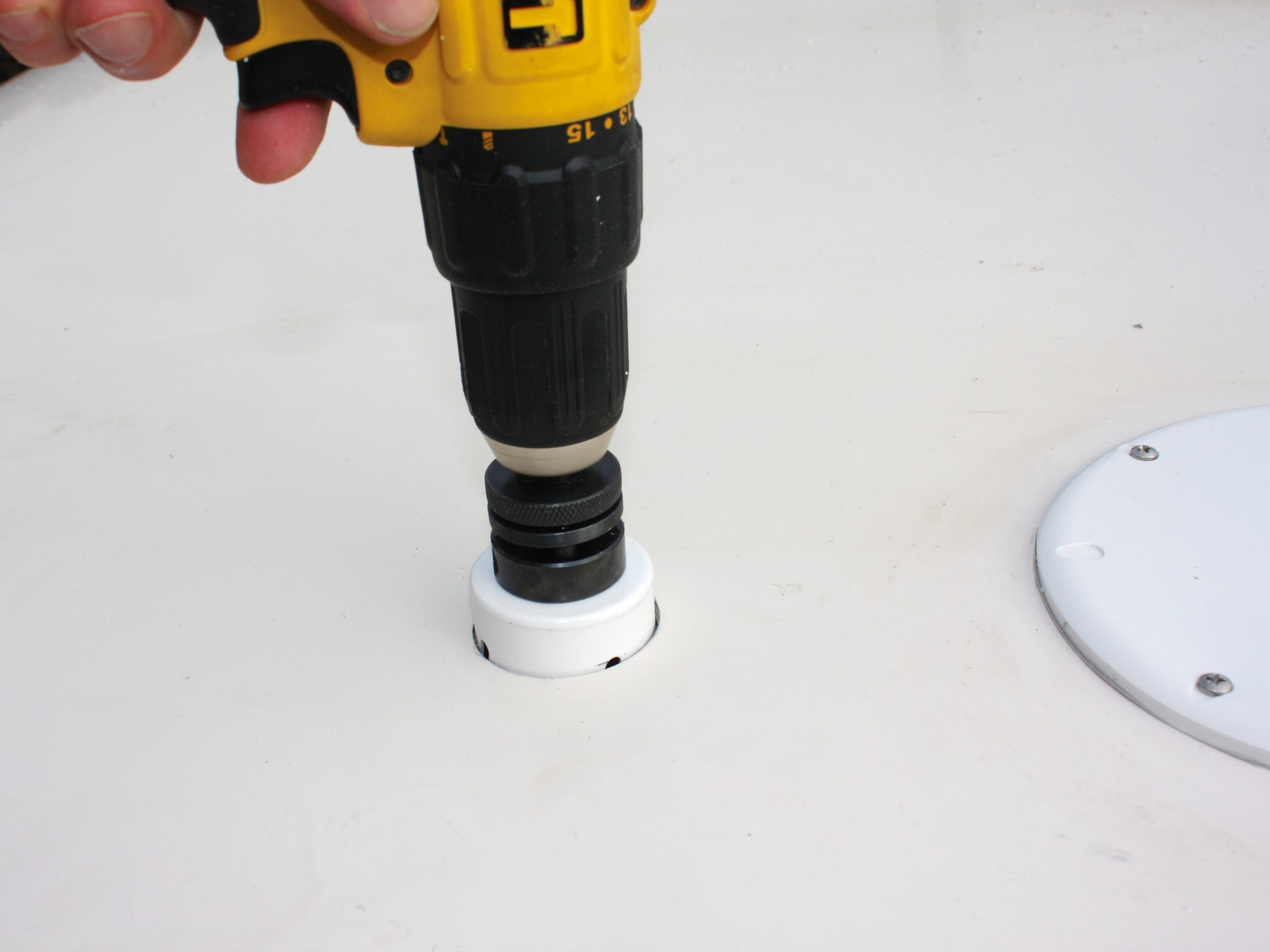
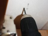
With the position selected, carefully drill a pilot hole up through the ceiling and roof. This must be vertical!
With that done, use the 50mm hole-cutter to cut up through the ceiling, then work down from the roof to cut out the rest. This leaves smooth edges both inside and out.
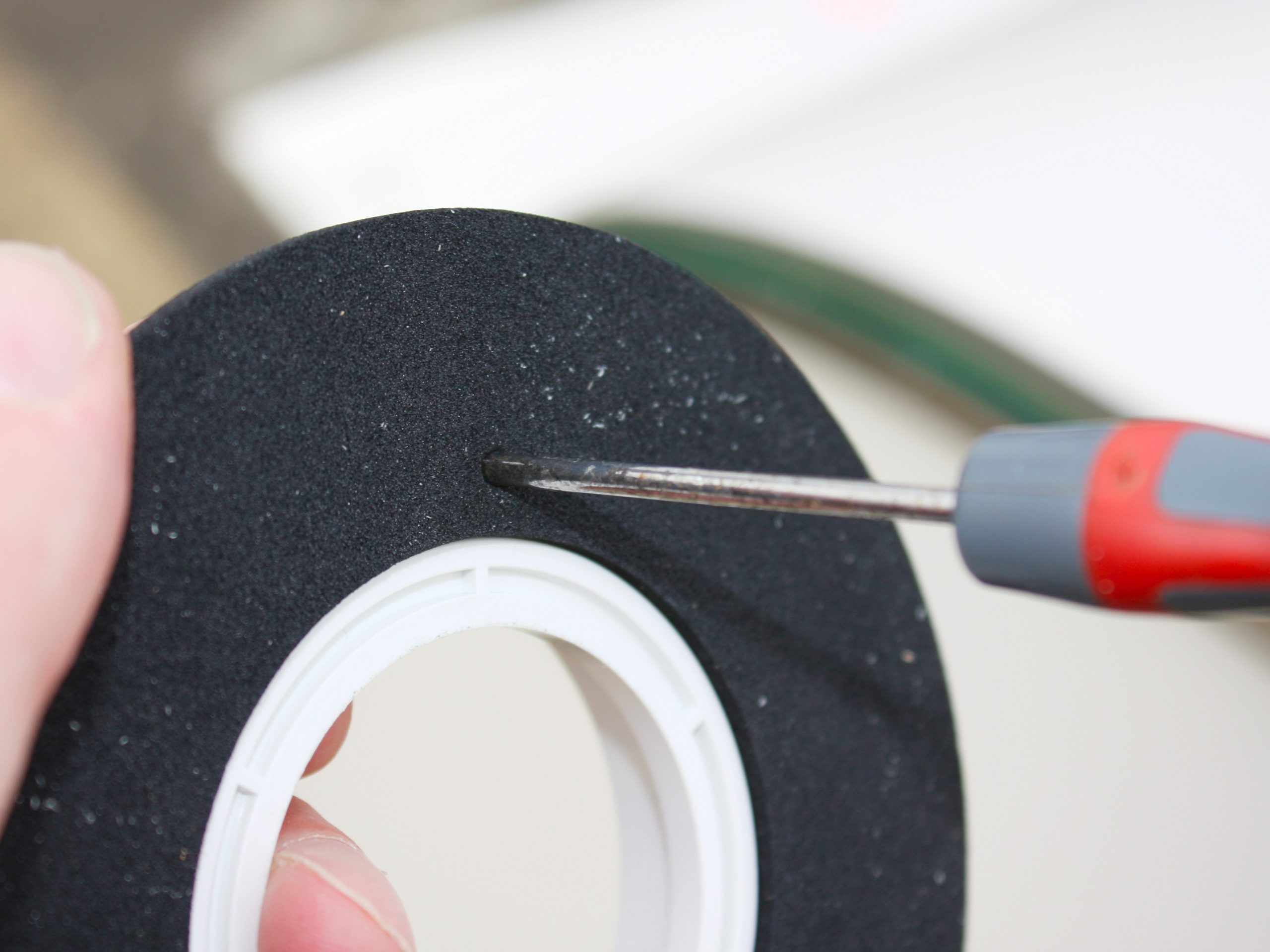
The mounting plate and foam seal are then screwed (using 16mm screws) to the roof, surrounding the hole.
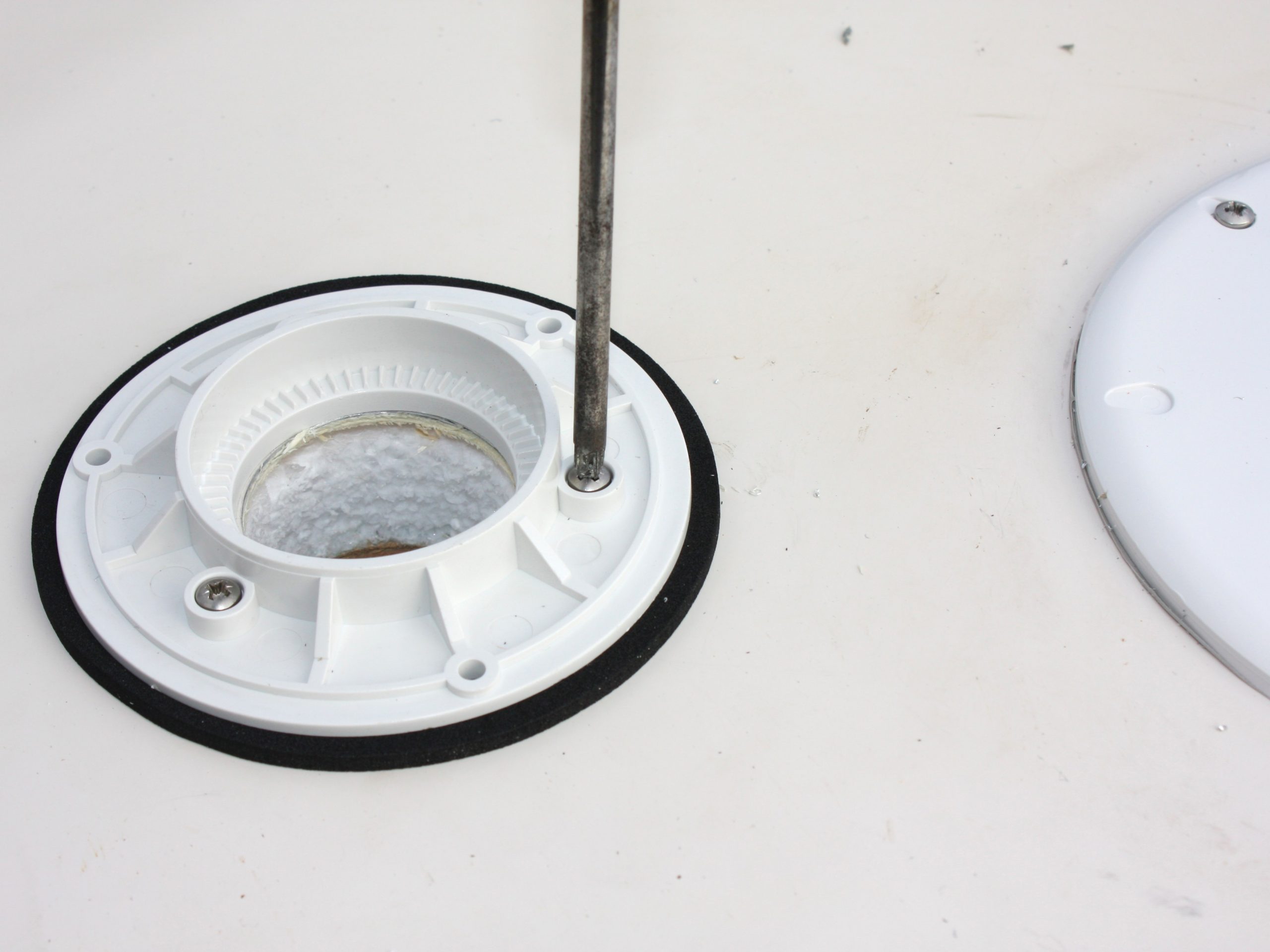
Taking the mounting foot, twist the central sleeve around inside the rubber gaiter until the tilt lines up with the angle of the roof and the screw holes in the mounting plate. Guide the mounting foot through the hole and secure to the foot (32mm screws).
Working inside the caravan, place the tapered washer and locking plate on the bottom of the central sleeve, which will be protruding through, and tighten, ensuring the assembly is vertical.
With that done, secure the locking plate with 16mm screws. The antenna is then assembled.
The final stages
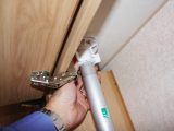
Insert the driveshaft into the ‘gearbox’ of the antenna and turn anti-clockwise until the ‘gearbox’ has rotated through 90° and is vertical.
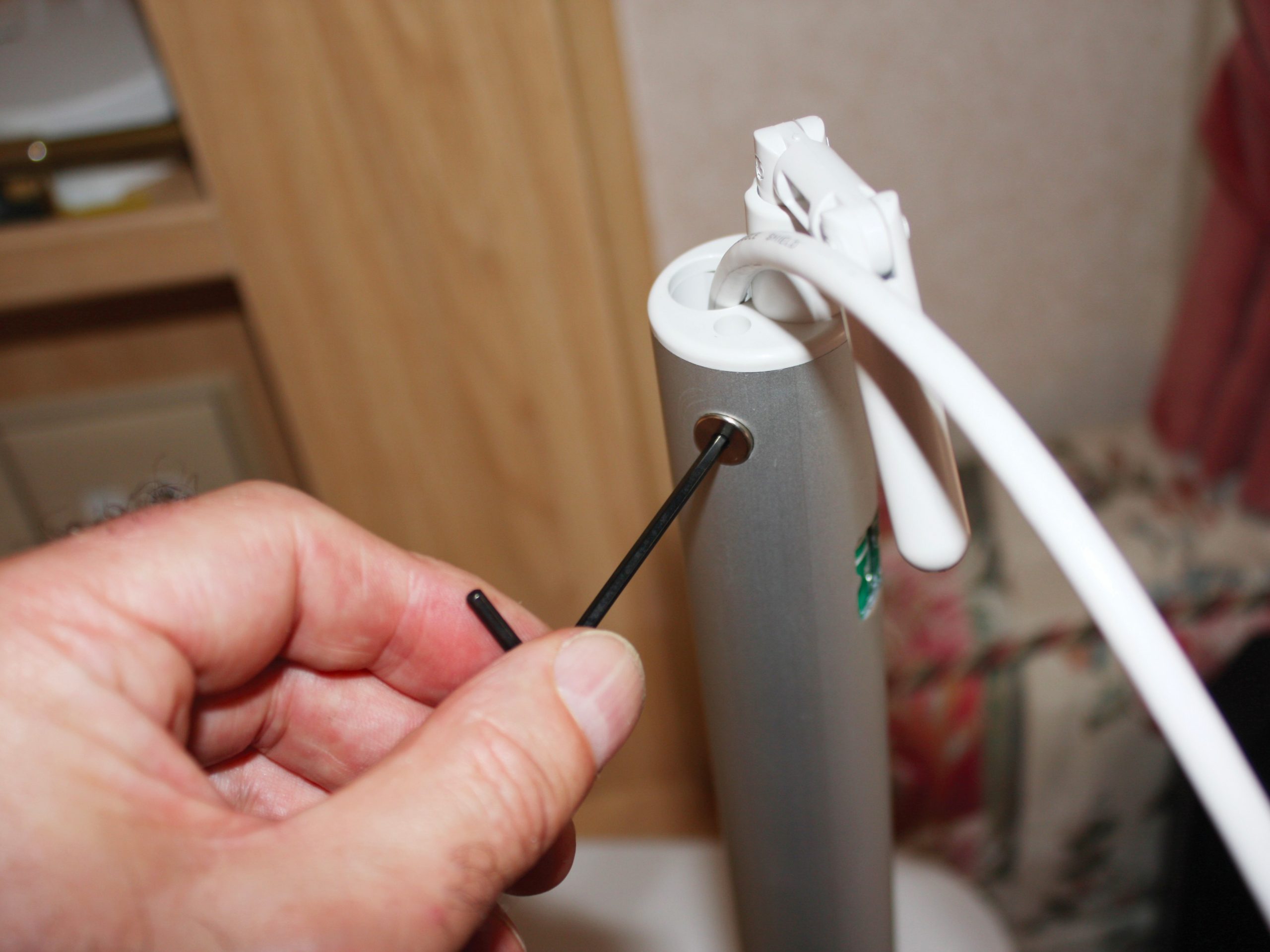
Pass the coaxial cable through the metal mast and then push the mast over the three ‘O’-rings (smear the rings with washing-up liquid to help). Secure the mast with one of the M5 bolts provided, using the allen key.
Ensure that the H/V indicator is threaded fully down on the winder mechanism, and then slide the assembly into the mast, ensuring the driveshaft locates in the ‘gearbox’ and the H/V indicator is centred in the window.
Secure with the other M5 bolt. Both bolts must be flush with the mast. Feed the cable and mast through the mount from the top, attach and secure the locking collar.
Locate the amplifier, where it’s near the mast and accessible. I put ours close to the original position so that the cabling could be reused.
Ensure there is enough coaxial cable between the mast and the amplifier for when the mast is raised. Do not allow any kinks in the coaxial cable or for it to be pulled tight in any position.
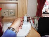
Connect the 12V battery. Test the antenna with a TV and radio.
Because the antenna’s amplifier has a 12V supply that will need fitting, ensure that the 230V mains and 12V battery are disconnected
The exercise was almost a direct replacement of the original