


ONCE YOU’VE WORKED out which air-conditioning unit you’re going to use and where to site it (click here for reader Tony Brown’s advice on preparation), you can follow Tony’s guide to the fitting procedure.
WARNING This project involves electricity, so disconnect the supply first. If you’re in any doubt about your competency to do the work, contact a specialist.
Tools and materials
Car ramps or axle stands; twist drill set; electric drill; jigsaw; hole saws and arbor (the clamp for the hole saws — see below); pliers and screwdrivers; under-body seal; masking tape; screws and washers to attach floor grilles; air intake grille; three cold-air outlets; cold-air ducting; underfloor sleeving, if necessary; interior and exterior duct clips; fused connection unit.
HOLE SAWS AND ARBOR
I had to cut 14 holes of three different diameters, and to do that correctly it’s absolutely essential to have tools that are man enough for the job. A multi-blade hole saw with a backing plate with concentric rings is not suitable. The blades will blunt quickly.
It is worth buying a good-quality arbor with interchangeable, cup-shaped cutters before starting this project. It won’t break the bank and will be ideal.
You can order arbors and hole saws from Screwfix (tel 0500 414 141, www.screwfix.com). The relevant catalogue numbers are in bold:
12437–12 11mm quick-hitch arbor
19804–12 70mm hole saw for ducting
18572–12 86mm hole saw for sleeving
18528–12 57mm hole saw for infrared remote-control receiver.
STEP 1
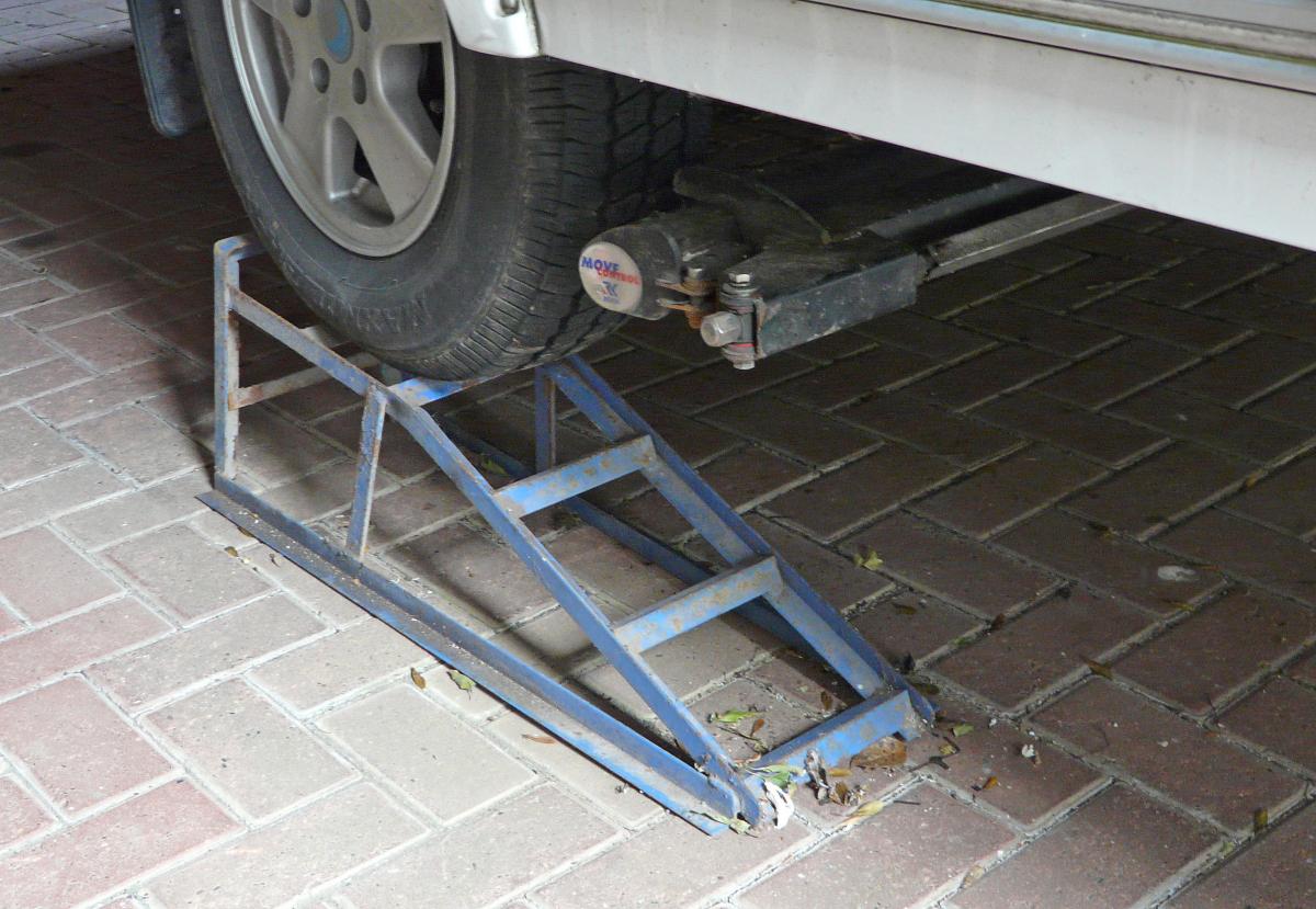
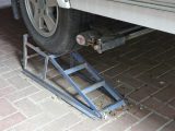
[tl:gallery size=197×134]Run the van up onto car ramps and chock the wheels securely, or jack it up on axle stands for safety. Lower all the legs to improve stability. This will be a great convenience during the installation and, of course, essential if you are planning to run your air ducts under the floor.
STEP 2
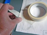
[tl:gallery size=197×134]Use masking tape to attach the template provided to the selected locker floor. Note that the cooling unit can be rotated through 180˚ if required to avoid underfloor obstructions. Wherever you decide to site the unit, make sure you observe the manufacturer’s instructions for minimum wall clearances.
STEP 3
[tl:gallery size=197×134]Check carefully for underfloor obstructions by measuring from a nearby ventilation hole or cable route. Then drill a small pilot hole through the centre of each of the three floor openings and recheck the underside. This will give you the chance to make any last-minute siting changes that may be needed.
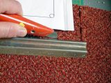
STEP 4
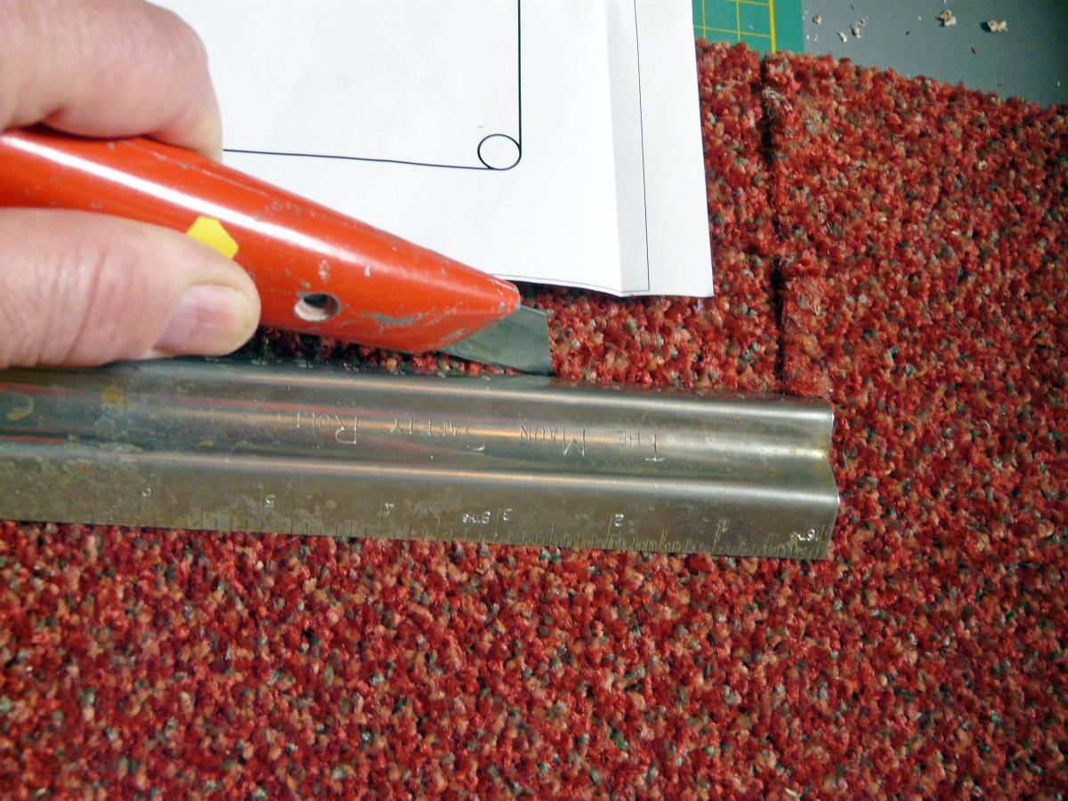
[tl:gallery size=197×134]After double-checking the dimensions of the cooler unit, trim the carpet to cut out the exact area that the cooler will occupy. Use a craft knife with a sufficiently sharp blade and a firm, metal straight edge. This should ensure the cooling unit has a flat surface to sit on once it has been installed.
STEP 5
[tl:gallery size=197×134]The best way of achieving a clean cut-out is to drill a hole at each corner of the two oblong openings (within the a that the hole will occupy) and then use a jigsaw to join up the corner holes. Use a 50mm hole saw for the condensation drain. Drill holes for the retaining brackets according to the template.
STEP 6
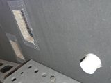
[tl:gallery size=197×134]Use a 55mm hole saw to drill the hole for the remote control receiver on your chosen furniture unit. The hole should be in a place at which you can easily point the remote control to maximise ease of operation. Attach the unit and route the control cables to the cooling unit location.
STEP 7
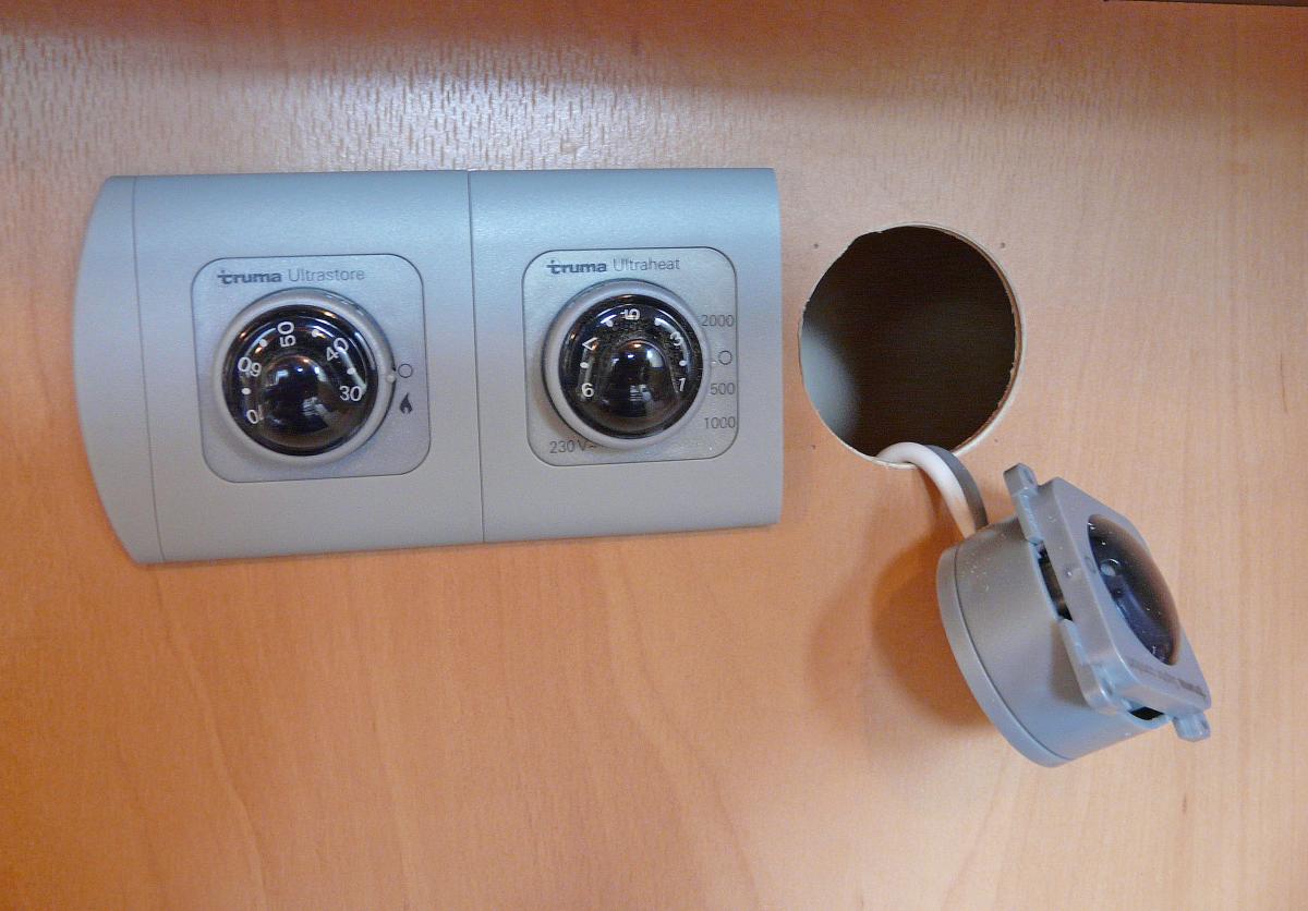
[tl:gallery size=197×134]If you already have matching heater controls with which you can line up the receiver, remove the end trim before drilling the hole for the receiver. Refit the end trim to the new remote-control receiver to produce a neat, original-looking result.
STEP 8
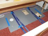
[tl:gallery size=197×134]This picture shows the three floor holes. Fit the blue retaining brackets and straps as shown, insert the condensation drain plastic liner (left) and plug in the remote-control cable before sliding the cooling unit into place and fastening the two retaining straps.
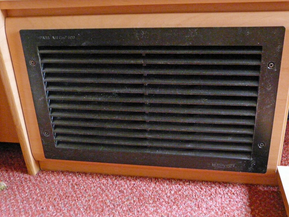
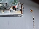
STEP 9
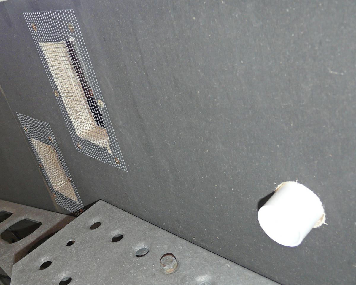
[tl:gallery size=197×134]Here’s a view from underneath the floor. Use screws and washers to attach the floor grilles to the underside of the new openings. At a later stage, an underbody seal will be used on the cut edges of the floor holes to give maximum protection.
STEP 10
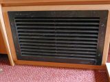
[tl:gallery size=197×134]Use a jigsaw to cut a hole for your air intake grille (minimum 300mm), which should be sited in the side of the bedding locker, as near as convenient to the unit’s air intake. This grille can be supplied as an extra with the unit or sourced separately from hardware stores or online suppliers.
STEP 11
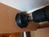
[tl:gallery size=197×134]Drill holes for the three cold-air outlets where there is easy access for the ducts. These should be equally distributed along the length of the van and high up to allow the cold air to drop down. The size of these holes may depend on your outlet fitting, but in this case they were 65mm in diameter.
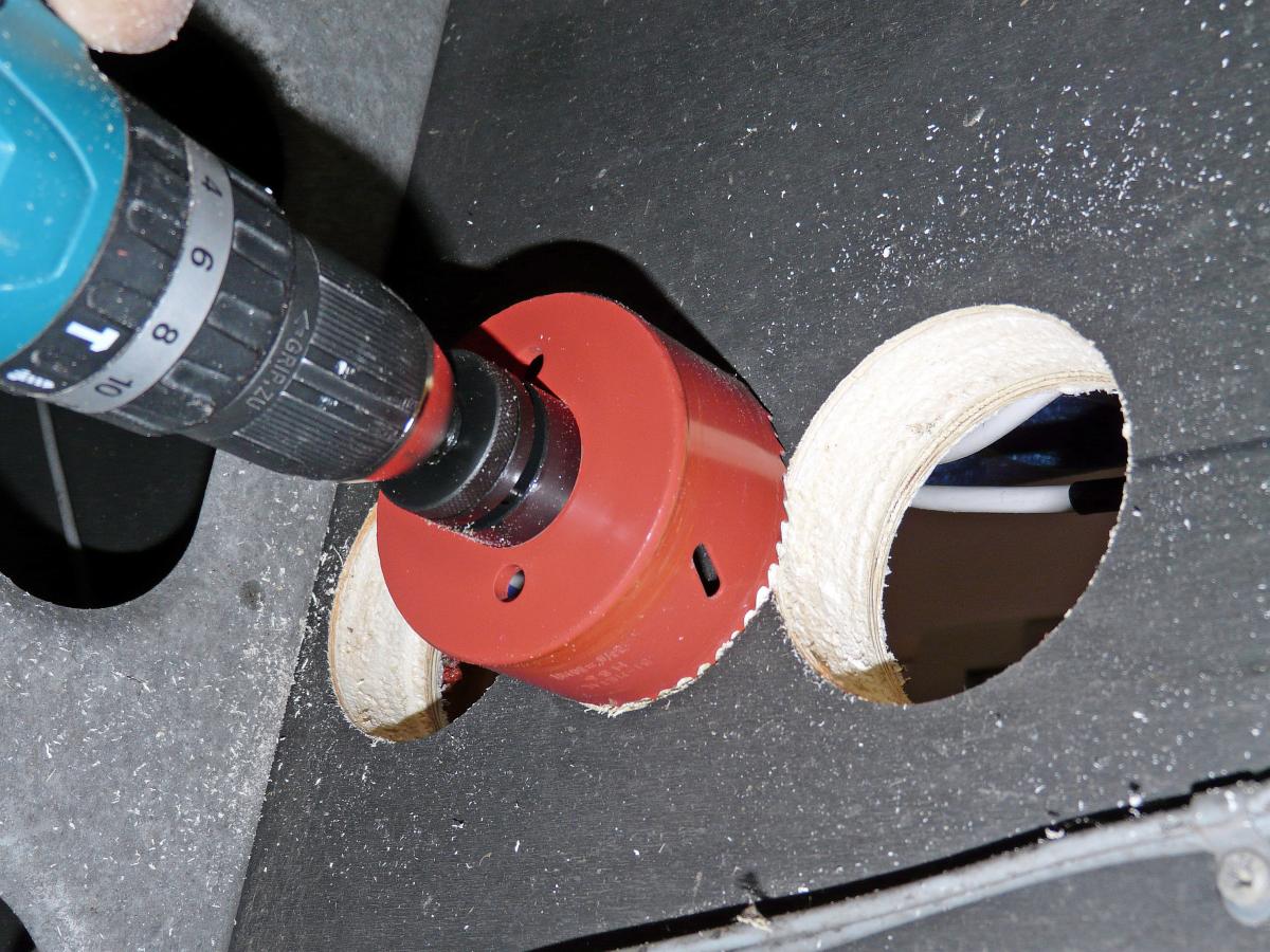
STEP 12
[tl:gallery size=197×134]After checking under the floor, drill any floor holes with an 80mm hole saw to accommodate the waterproof underfloor sleeving. Here it was more convenient to drill all six holes from below. Also, 65mm holes will be required in partitions through which the interior air ducting passes.
STEP 13
[tl:gallery size=197×134]If you are routing the duct under the floor, start by loosely fitting all the lengths of waterproof black underfloor sleeving, leaving the ends exposed a couple of centimetres above the floor inside. If it’s more convenient, you can then leave the sleeving in place under the van, provided you remove the two ends from their floor holes so you have a straight run of sleeving.
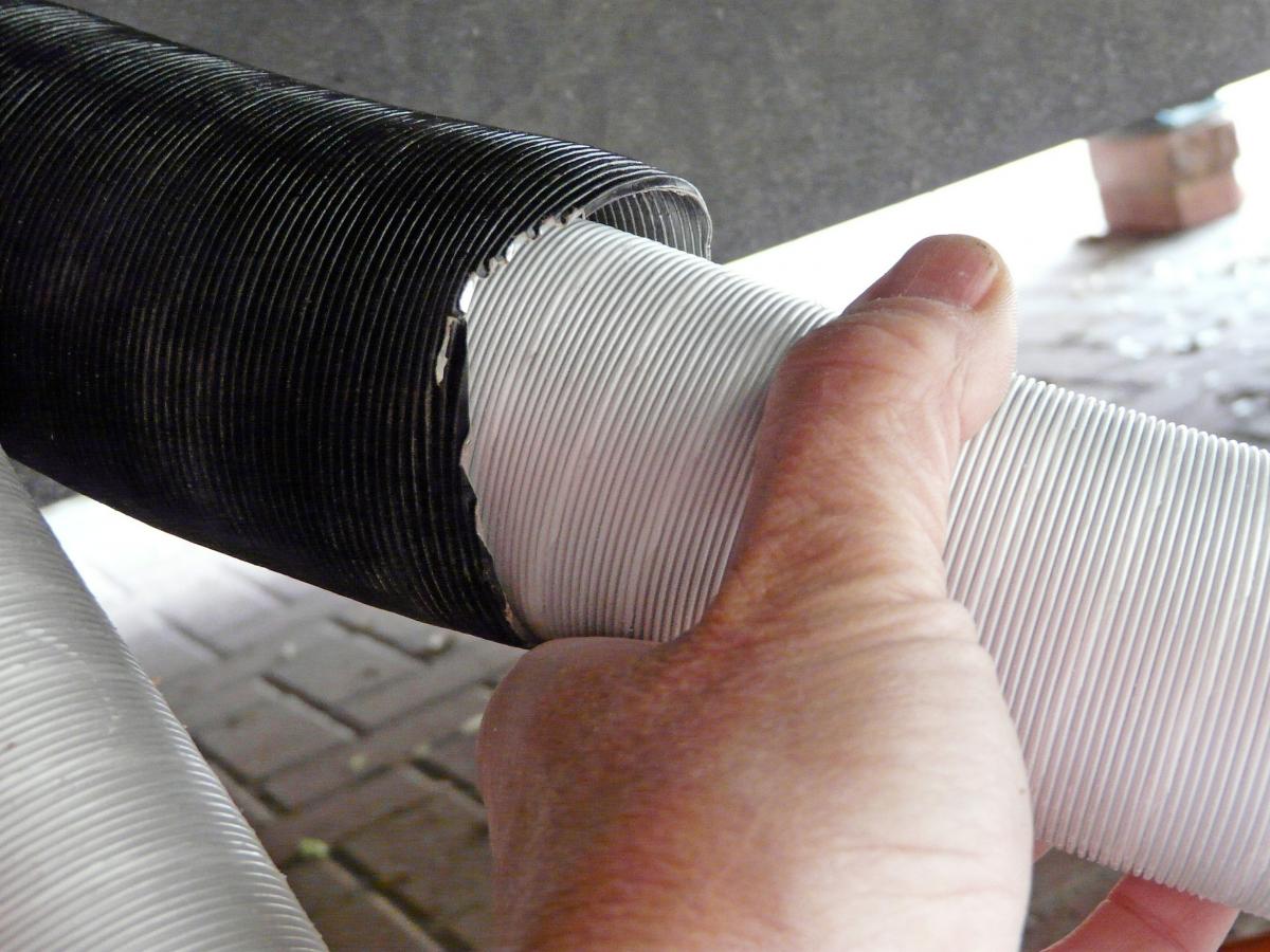
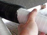
STEP 14
[tl:gallery size=197×134]Push the internal ducting into the sleeving with a stabbing or twisting motion to overcome the friction between the two ridged tubes. Keep going until you have the desired length of duct exposed at the cooling unit end to connect to the cooler later. Feed both ends of the underfloor duct through the floor. As you insert the ducting, make sure there are no cuts or abrasions in the material.
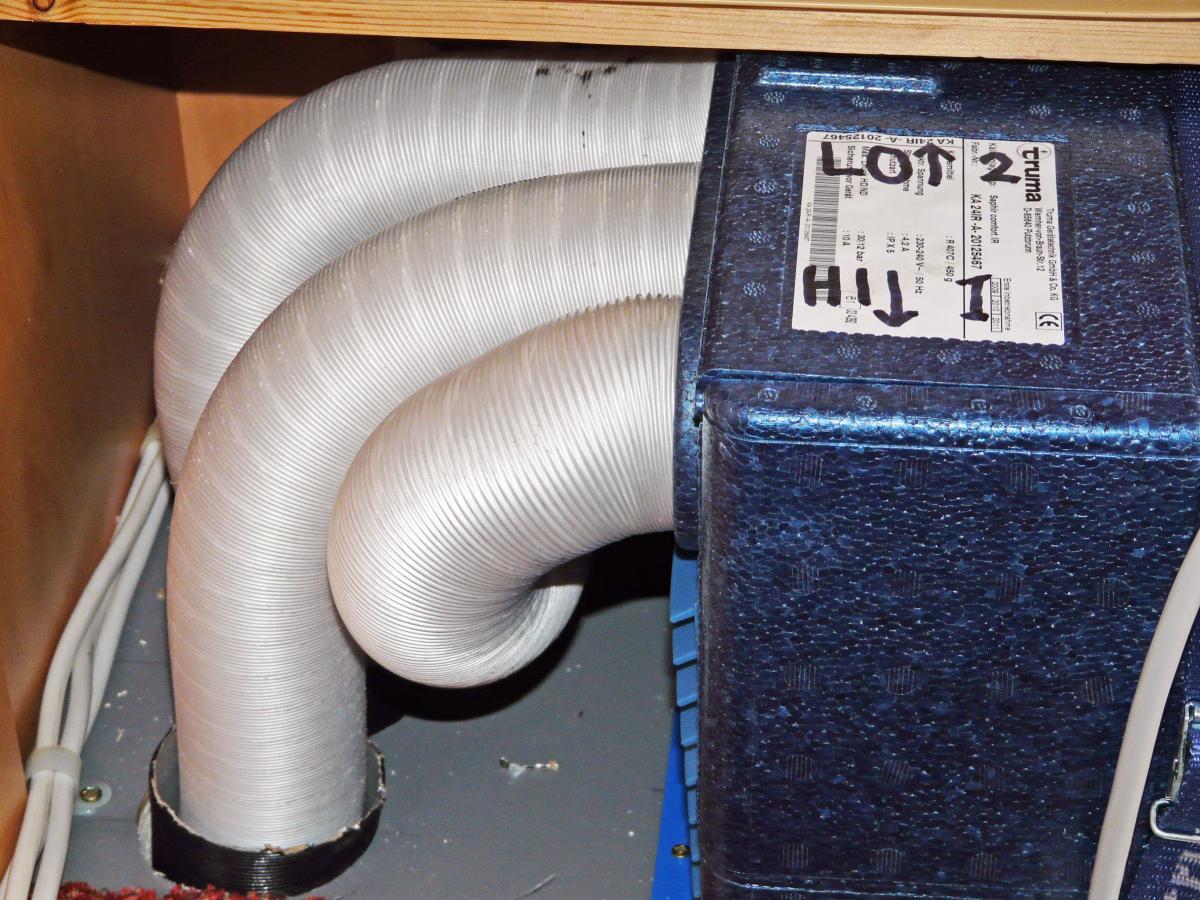
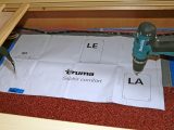
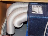
STEP 15
[tl:gallery size=197×134]Attach the internal ducting to the cooling unit and feed to each outlet. It’s best to allow sufficient length to allow any ducts to connect to any of the three cooling unit emitters. This is because one outlet is of higher air flow and designed for the longest length of ducting (maximum 8m). Later, tubes can be changed around according to the cooling pattern you require.
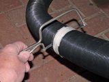
STEP 16
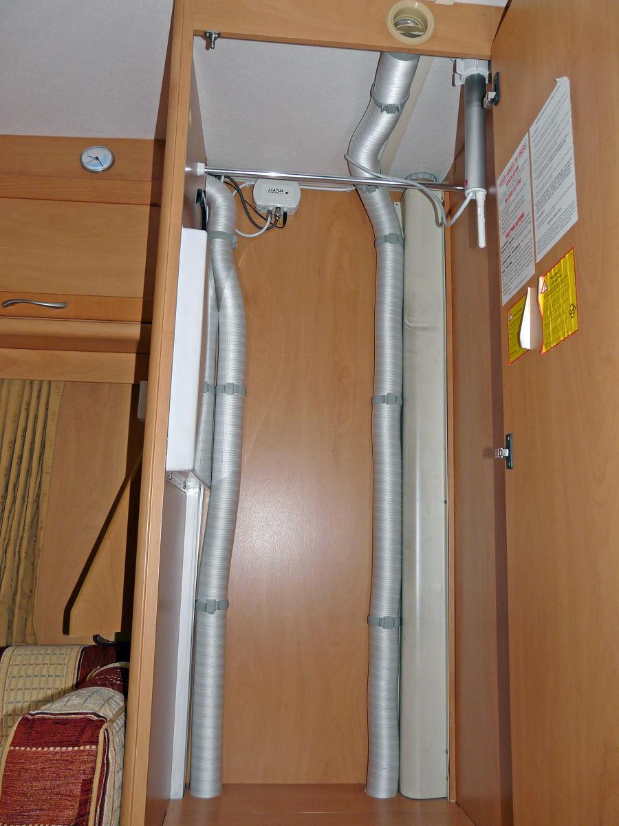
[tl:gallery size=197×134]Different-sized duct clips are provided for interior and exterior use and these can be fitted once you’re happy that all the tubes are properly secured in place. Here you see the ducting neatly clipped into the wardrobe corners. If there’s a tendency for the ducting to pop out of the cooling outlet nozzles, you can put a small self-tapping screw in the back of the nozzle through the duct.
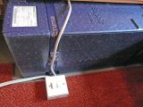
STEP 17
[tl:gallery size=197×134]Get your electrician to fit a switched, fused connection unit near the cooling unit and connect the unit flex. If you have a power point within easy reach of this flex, a plug could be fitted to the flex, but you should not attempt any mains electricity installation unless you are qualified to do so. We’d also recommend having an independent electrical safety check done once the job’s finished.
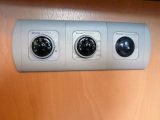
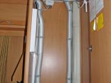
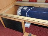
STEP 18
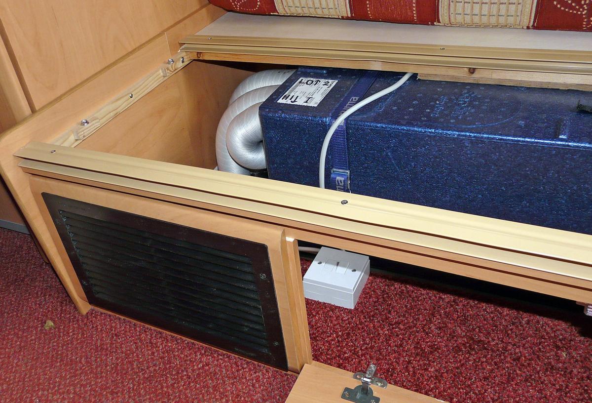
[tl:gallery size=197×134]This is our completed unit installation. The final job is to switch on the fused connection unit and point the remote control at the receiver to turn on the unit. Then set the temperature to 16C and the function to ‘Comfort’ for a cooling test. All being well, your new unit should be more than adequate to keep you free from sweltering conditions in even the warmest climes.
For details on the unit Tony fitted to his van, click here.
Get £50 for a clever fix
If you’ve carried out any DIY, then we want to hear about it. Email [email protected] or write to the address on page 121 with at least 150 words and a couple of photos (digital or print). We’ll pay £50 for any we print.