


Many new caravans come with a fitted radio/MP3 player that links to an external source via Bluetooth to play music through the caravan’s speakers.
However, there could still be times when the ‘Aux’ (auxiliary) jack socket might be required, such as playing something from a laptop or TV, neither of which are necessarily going to be Bluetooth compatible.
Alternatively, the radio unit might not support Bluetooth, like the one in my son James’ ageing Abbey. The radio was upgraded a few years ago, but doesn’t have Bluetooth.
James mentioned a while ago that he’d like to wire up an external Aux stereo socket on the dresser unit where the TV perches, or where he and his wife, Lisa, put their phones/tablets/laptop, rather than having a long lead trailing from there into the overhead locker, where the radio is.
The original thought was to run a cable directly to the radio and plug it into the back of the unit, but we decided it might be better to put another stereo socket inside the locker and run a short lead from there to the radio.
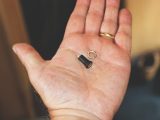
I sourced a couple of 3.5mm stereo sockets from eBay (they’re easily obtainable from several other places, though), and we already had a 2m audio cable with 3.5mm jack plugs on each end in our ‘supplies’, from which we removed the jack plugs.
Tools and materials
The only other items needed to complete the job were:
- Cable ties
- Heat-shrink of various sizes
- Selection of screwdrivers
- Wirecutters and strippers
- Electric drill and selection of drill bits (the largest we needed was 8mm)
- Fine-tipped soldering iron and solder
- Solderer’s clamps
- Heat gun
Before starting the job, ensure that the 230V mains and 12V battery are disconnected.
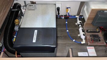
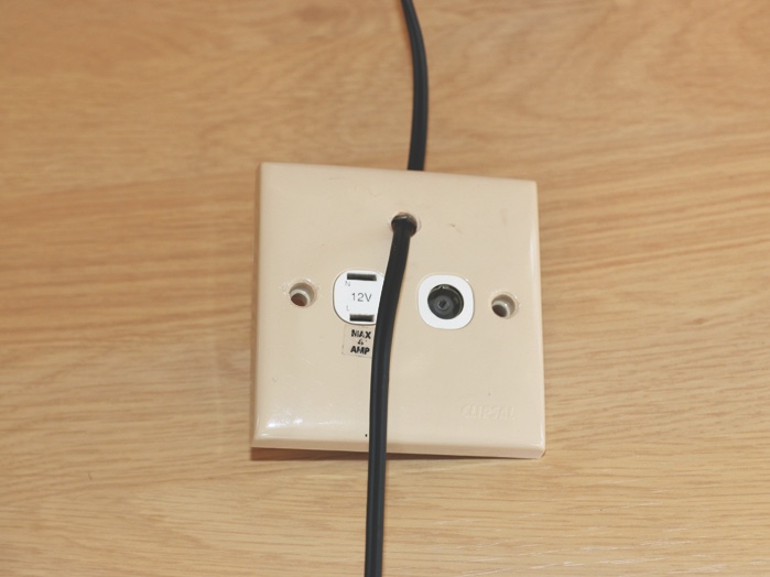
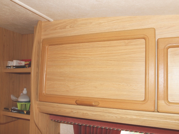
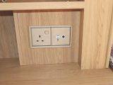
The first step is to decide where the Aux stereo socket is going to be fitted. For us, the simplest solution was to use the factory-fitted 12V and TV aerial socket facia on the dresser unit, because of the way in which everything has been boxed in on the Abbey.
So after carefully prising out the screw caps, we unscrewed the unit from its housing. Making a note of where each of the various wires and cables was attached, these were disconnected.
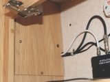
Luckily for us, the end panel inside the overhead locker next to the dresser is removable, so after removing a couple more screws, we had access to the area behind it.
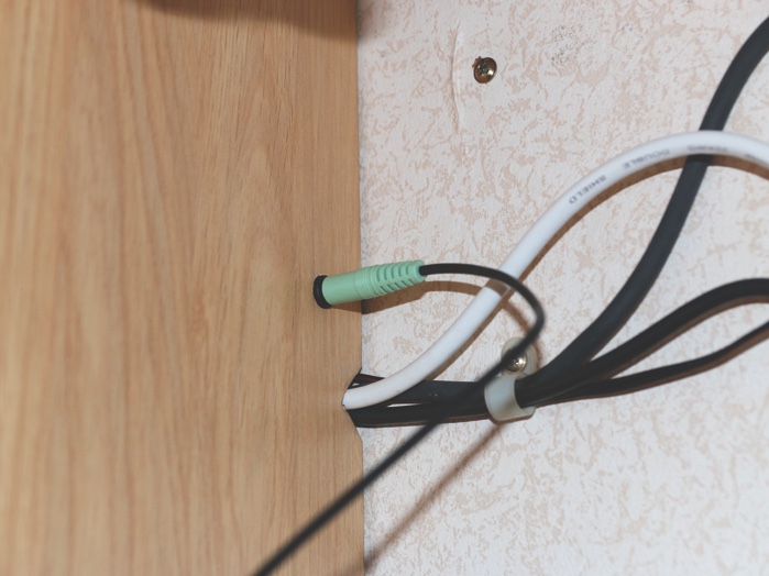
Next came what was possibly the most difficult part of the process: feeding the audio cable from the dresser unit into the overhead locker.
James formed a pull-through using a cable tie to link the ends of the cable together, and hey presto, we had one end where the facia fits and the other up in the overhead locker.
As the cable follows the TV antenna lead, we secured the two together using cable ties, so that it wouldn’t be snagged behind a drawer or affected by the heat from the gas fire’s flue.
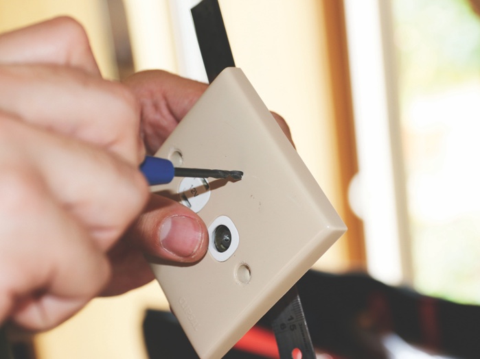
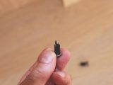
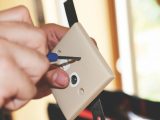
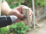
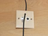
Starting with the facia plate, the position for the stereo socket was measured and marked before a small pilot hole was drilled. This was gradually opened out to the 8mm required for the socket.
The nut that secures the socket was fed onto the audio cable and then the end of the cable was fed through the facia plate hole from the back.
Wiring up
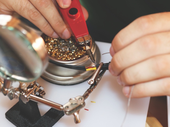
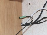
Working with that end of the audio cable, its two parts were separated for a few centimetres before the outer black insulation was trimmed, to reveal the red and yellow internally insulated wires, together with bare earth wires attached to each. A short section of the red and yellow insulation was trimmed to expose the internal wires.
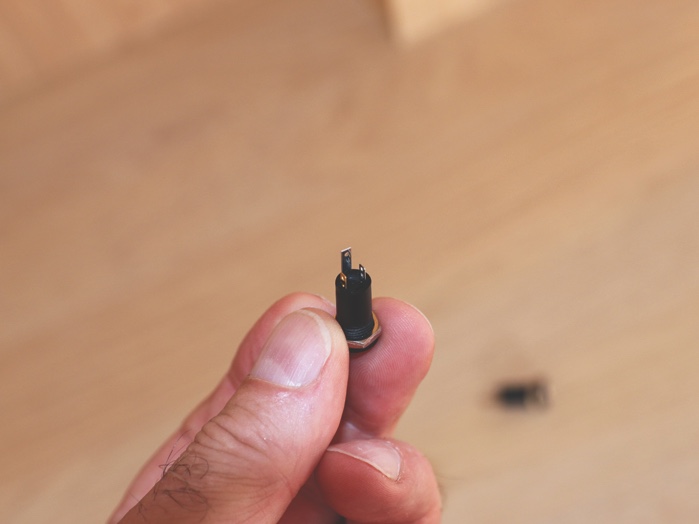
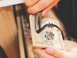
Looking at the back of the stereo socket, there are three terminals: two short ones and a longer centre one. Looked at more closely, the shorter terminals are different colours (silver and gold), to identify left and right stereo connections.
It doesn’t matter which wire is connected to which, provided that the same wire is attached to the corresponding terminal at the other end of the cable. The longer terminal is for the earth wire(s).
Before soldering the wires to the terminals, we slid a short length of heat-shrink onto the cable, large enough to cover the end of the stereo socket and the three wires, together with smaller sections over the red and yellow wires.
The wires were then soldered to the respective terminals (in our case, red wire to gold terminal), and the smaller heat-shrink secured over them, before we finally covered the whole thing with the larger piece of heat-shrink.
The stereo socket was secured to the facia plate using the nut and then the facia plate (complete with other connections) was returned and secured into its housing on the dresser unit.
Cable ties
A similar method was used at the overhead locker end of the cable; although to stop the nut from that end’s stereo socket being lost, a cable tie was attached to the audio cable before the nut was slid onto the end of the cable. Of course, a hole had to be drilled through the end panel that we had removed. Remember to solder the same coloured wire to the corresponding terminal on the socket (in our case red wire to gold terminal).
With the stereo socket now secured to the panel, the panel was replaced.
The 12V battery was then reconnected, and it was time to try the sockets.
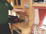
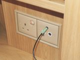
We plugged a cable between the back of the radio and the stereo socket on the overhead locker panel (which can now become a semipermanent fixture), and then another similar lead between the TV’s headphone socket and the socket on the facia (James needs to get some shorter leads for this now!). Then we turned on the TV.
All I will say is that the sound coming through the caravan’s speakers has a much better quality than that coming from the ‘tinny’ ones on the TV!
IMPORTANT!
Electricity is dangerous. Disconnect any mains supply and the 12V battery before starting DIY work. Seek the advice of a professional if in doubt. Future Publishing Limited, the publisher of Practical Caravan, provides the information in this article in good faith and makes no representation as to its completeness or accuracy. Individuals carrying out the instructions do so at their own risk and must exercise their independent judgement in determining the appropriateness of the advice to their circumstances. Individuals should take appropriate safety precautions and be aware of the risk of electrocution when dealing with electrical products. To the fullest extent permitted by law, neither Future nor its employees or agents shall have any liability in connection with the use of this information.
The sound coming through the caravan's speakers has a much better quality than that coming from the TV